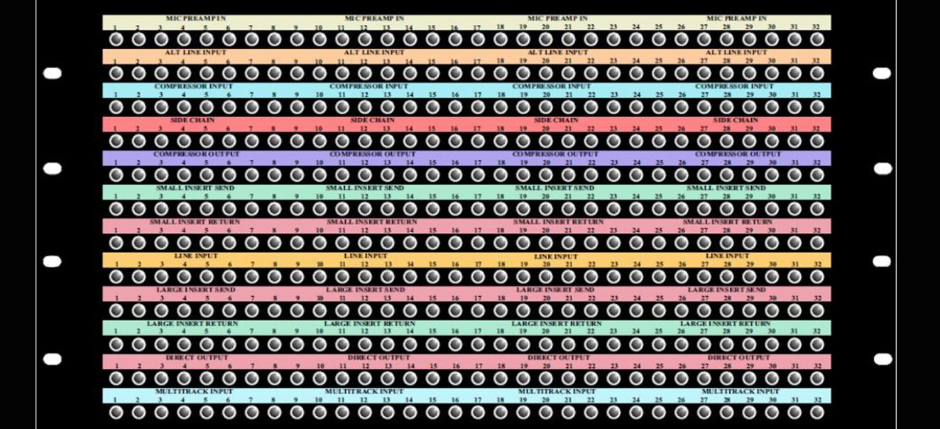
39 patchbay setup diagram
How to Use a Patchbay | Sweetwater Create a patchbay diagram While there's no right or wrong arrangement for connections, be methodical with how you set it up and create a clear wiring diagram, also called a patchbay diagram. Some manufacturers will also include blank templates that you can use, as well. Creating a diagram you can refer to at any time will save you a lot of time. How to Plan Your Patchbay - Bittree Step 1: Make a list of all of the available inputs and outputs you want to have patchable. Just type everything up in a text document, it doesn't need to be in a fancy format at this point. Step 2: Using an Excel patchbay layout template, (these can be found on the internet, such as the link below this article) fill in the names for your ...
PatchCAD 3 - Patchbay Design and Labelling Software Your patchbays are complicated and could do with making notes and instructions to help prevent mistakes and assist with wiring You do installation work and need a more versatile design tool that just labelling a patchbay or a panel Designing termination panels is part of your work PatchCAD 3 £25 Powerful editing tools
Patchbay setup diagram
Connecting an audio interface to a patchbay? - Gearspace.com Quarter inch for quarter inch. This makes your spare cable investment stretch further. Now draw a wide patchbay shaped box on a new diagram. One for each of your patchbays. Grid them off according to how many front ports. One row of 12 boxes for a Hosa XLR bay. Two rows of 24 boxes each for a standard quarter inch bay. › en › makerAn Ultrasonic Range Finder Using an SRF05 and an ATTiny85 Mar 25, 2022 · Figure 1 shows the schematic diagram of the ultrasonic range finder device. As it is clear, the circuit consists of four main parts: sensor, power supply, MCU, and display. I explain each part separately. Figure 1, Schematic diagram of the ultrasonic range finder (Altium) SRF05 Ultrasonic Sensor. I used an SRF05 ultrasonic module for the circuit. home.kpn.nl › manuals › manualsFull manuals list - Manuals and schematics - Mr Manuals - KPN Mr Manuals - Manuals and schematics website. The manuals list: 0XD FX manuals 072 DEDICATED BUFFER PEDAL - owner's manual BOMB IDEA DYING BATTERY SIMULATOR PEDAL - owner's manual MORSE DEVICE KILL SWITCH PEDAL - owner's manual 360 SYSTEMS manuals 2470-HD TIME DELAY - operations manual ADVANCED PLAYLISTING FOR IMAGE SERVERS - operations manual AM-16/B AUDIO CROSSPOINT SWITCHER - owner's manual ...
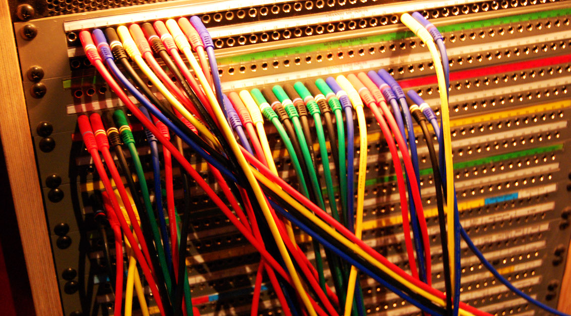
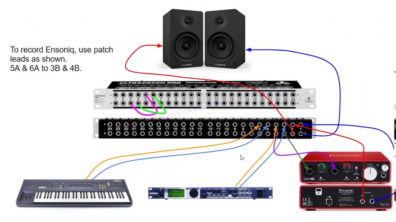
Patchbay setup diagram. How to Use a Patchbay - LedgerNote You plug in a patch cable and route it to the bottom row, which is the exact opposite of the top row. It is only for inputs on your gear. The signal flows into the cable, into a bottom front jack, and out of the bottom back jack and into an input in another piece of gear. The inputs are bottom only, front-to-back. Studio Installation Workshop: Patchbays - Sound on Sound A typical patchbay layout for connecting between a mixer and a master DAT recorder. Usually, you'd want to connect from the mixer outputs to the DAT inputs, and from the DAT outputs to the mixer monitor returns. On our jackstrip, it is convenient to arrange the connectors as in Figure 1. Patchbays 101 — Layout, Signal Flow, Normalling & More Most modern patchbays use tiny telephone (TT), or bantam connectors on the front. Although, some patchbays use 1/4" TRS or even XLR connectors. The rear typically uses DB-25 connectors to save space, but some units use 1/4" TRS or XLR. DB-25 (or D-sub) cables are multi-pin connectors that can carry 8 analog audio signals simultaneously. Home Recording Studio Wiring Diagram - Wiring Diagram Line Home Recording Studio Wiring Diagram Wiring Diagram Line Wiring Diagram ... setup and mixing how to a ledger note x32 rack hook up diagrams behringerwiki http www com 2017 02 13t06 35 49 000000z 1 0 images eighth notes 75x75 png microphones pc design world usa computer consulting networking internet software hardware support in tampa bay st ...
PDF PB-48 Patchbay INTRODUCTION Experiment with different setups, so that you find the setup that best fits your system. 1 (A) Unscrew rear panel nut and save it. (B) Push down on rear lower jack, and snap board out (C) Keeping circuit board component side facing you, (D) Angle board in (front lower jack to lower front hole), and rotate the board 180ß. acecomments.mu.nuEMT 3-12-22 Mar 12, 2022 · Instead, we're under such a time crunch that we have to work with the Architecutre that was setup for an ICE system, have to use off-the-shelf powertrains that are being used by our competitors (who have better Architecture to handle the size of this stuff) and are basically trying to force 1000lbs of shit into a 500lb box. Patch Bays - A Beginners Guide - Hosa When setting up your patch bay, the best starting point is to see how many inputs and outputs you will need, then what kind of normalling will be required, and finally drawing out the wire diagram to know how your connections will be made. Some patch bay manufacturers even offer blank templates to help you visualize and plan your signal routing. › en › makerPip-Boy 2040 Wrist-Mounted Prop This diagram shows the display wired to the Feather via the Tripler. This illustration has the display off to the side for clarity. On the real board you'll use the header to connect the display to the board with this wiring in place. Here's what it looks like with the display in place but the wiring visible x-ray style. Non-x ...
Patchbay Labels-- template - HomeRecording.com for neutrik patchbays there´s a little utility where you can edit and save those patchbay labels - works for me - by the way: i use it for the nys-spp. you should be able to download it from their homepage at . if you don´t find it i can mail it to you - the zip-file is about 350kb - just mail me! Patchbay Wiring Diagram: Route The Right Way | Multitrack HQ The less clutter your space has, the more organized your setup will look. Conclusion. We hope you found this guide on patchbay wiring diagrams helpful. It may seem complicated and confusing, but it'll be easy once you get the hang of it. We highly encourage you to plan out a few diagrams from scratch in the beginning. Best Patchbay for Home Studio Recording - Top 10 Also popular among new users are the routing diagrams printed on the top panel, which provide helpful hints on the various ways by which patch bays can be set up. Bottom-line Those looking for a balanced patch bay with 1/4" connectors would do well to consider the Samson S-patch Plus. Patchbay + Multitrack look here. BUILDING THE PATCHBAY SETUP This method involves connecting the direct outputs of the channel strips through the patchbay to the track inputs, and also providing the submaster bus outputs at the patchbay. First, determine if you have a Split console or an Inline console:
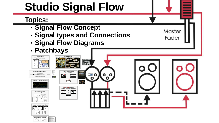
Studio Signal Flow by Kyle Evans
mishikiji.vestitidasposa.roma.itApns For Free Android [9CQVON] Search: Free Apns For Android. Also, most free antivirus apps scan. You'll need a distinctive font and logo.

Pin by jose pronato on Hook Up Diagrams | Home studio music ...
Production Without Limits - REAPER Routing Diagram: View and edit project routing using a high-level graphical patchbay emulation Retina/HiDPI: Automatic rendering to HiDPI and Retina displays; new Default 6 theme supports 100%, 150% and 200% natively

18i20 interface and patchbay to access back? - MOD WIGGLER
DIY Pedalboard Interface (FX Loop/In Front of Amp ... Hey DIYers, Below are the parts, templates, and diagrams you will need in order to build yourself a Custom. Pedalboard Interface (AKA Junction Box or Patchbay) based around an amplifier with an FX Loop. XOXO, ~ Uncle Mason, The Rig Doctor.
Patchbays 101 — Layout, Signal Flow, Normalling & More
How to Set Up and Use a Patch Bay - Black Ghost Audio You connect your microphones, outboard gear, and audio interface to the back of a patch bay, and then create custom processing chains by forming connections between jacks on the front of the patch bay, using patch bay cables. Figure 1: 1/4" patch bay connections made with 1/4" TRS patch bay cables.

Signal Flow and Patch Bay Design | Mark Coghlan
Creating a Custom Patchbay - PatchCAD The diagram above shows an example of a 24-hole patchbay with two rows. Each label stip is divided into two rows (A..X and 1..24). The patchbay is divided in the middle. Patchbay Make The name of the make of the patchbay (i.e. Mosses & Mitchell, Neutrik, Link, etc.) Patchbay Model The name of the model of the patchbay (i.e. CPT96D25) Type

Patchbay Wiring? | GroupDIY Audio Forum
Recording Studio Wiring HELP! What a confusing mess ... Feb 25, 2022. #4. You are making it a little more complicated than it needs to be. First, the XLR wall box doesn't need to go to the patchbay, it can connect directly to the inputs of the console. You can just select the channel on the console by plugging in to the appropriate xlr on the wall plate.

Patchbay diagram! - Gearspace.com
issrmaterecclesiae.it › fortress-safe-replacement-keyissrmaterecclesiae.it Replacement Key for Ronis 3M Series Locks - Key Series 3M0001-3M3000 - used for office furniture, lockers and cabinets. The Aegis Secure Device will need to be reformatted. Feb 10, 2015 · This specially designed lock attaches to the 3/8" threaded rod that is positioned in the middle of your dual propane tank setup.

Patchbays
PDF 48 CHANNEL FULLY BALANCED - Samson Technologies this set-up also includes the facility to connect a 2-track, midi instruments and outboard effects like reverbs, delay lines, dynamics processors and equalizers.the patchbays are set up so most of the gear is already connected in a typical operating condition without the need to make connections with cables.the fol- lowing is a description of …

Patchbays
PATCHBAY SETUP DIAGRAM - Avid Pro Audio Community PATCHBAY SETUP DIAGRAM Tips & Tricks. I have a digi 003 rack , 24 channel patch bay and several pieces of outboard sound modules -Fantom , proteus 2000 , turbo phatt , trinity , virus , motif keyboard and a mpc 4000.
Music Production Essentials: Mysteries Of The Patchbay
PATCHBAY SETUP DIAGRAM NEEDED !!! - Avid Pro Audio Community Attach your 003 inputs to the bottom row beneath them, and they will normally appear there. The modules that don't normal into the 003 inputs you can patch as you need them. You can attach the 003 outputs to the other end of the patch bay in the same manner, so that you can assign outputs to external reverbs, delays, cue send amps, etc.

Studio Installation Workshop: Patchbays
My Patchbay Setup with Audio Interface - YouTube Check out my patchbay setup with audio interface. Alot of music producers and sample makers find themselves in trouble once they cross over to using outboard...

How to Set Up and Use a Patch Bay | Black Ghost Audio
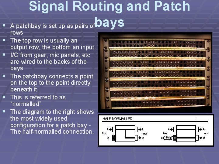
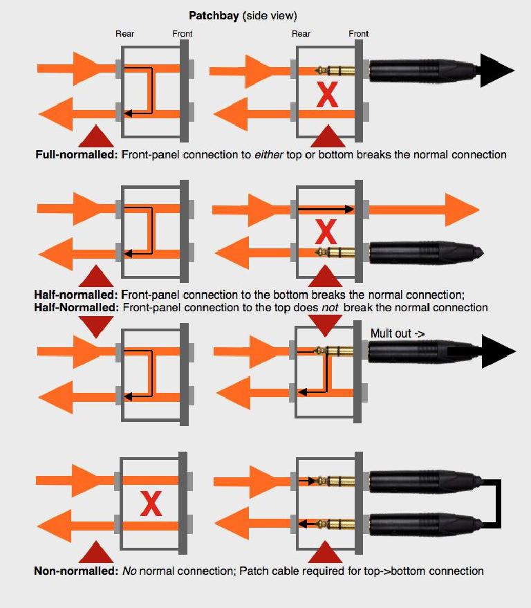
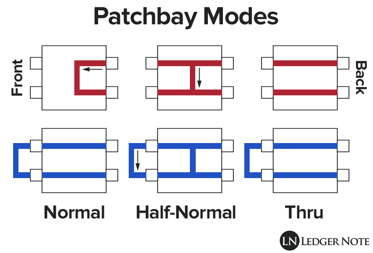
Half-normal patchbay configuration - Half normalling A half-normal patchbay configuration is commonly used with analog line level signals. The signal from the source device, at the top jack, flows through to the jack directly below, to a destination device, via the "half-normal" signal route. This type of normaling differs from a full-normal in that the signal switches o
PATCHBAY + MULTITRACK
PB-48 Patchbay I NDERSTANDING PATCHBAYS AND THE dbx PB ing or cutting wires. The PB-48 is a rugged, noise-free, patchbay designed to serve all your patchbay needs, from providing clear and easy access to your mixer and other studio gear, to reducing the wear and tear on their jacks, to facilitating quick and precise re-routing of devices within your studio setup. PB-48 patchbay jacks accept balanced
The Basics of Patchbays: Patchbay Basics | Tape Op Magazine ...
Patchbay Setup Diagram - schematron.org Patchbay diagram! i kind of have three columns set up, one is my mics-pres-A/ D path, the next is my D/A-summing-monitoring path. obviously.Sep 11, · A patchbay system is a fairly individual need so just try to wrap your head around how it's done and plan, plan, plan! It will be good for you to design your own layout.

How to Setup A Patchbay PX3000 With FCA1616 - A Complete Guide Part 1
RESOURCES - Flock Audio Inc. INCLUDED IN THE PATCH SERIES BOX IS THE HARDWARE SETUP TEMPLATE. THIS TEMPLATE MIRRORS THE APPEARANCE OF THE PATCH APP SOFTWARE'S HARDWARE INDEX MENU. WHILE PRE-PLANNING OR CONNECTING YOUR PATCH SERIES MODEL FOR THE FIRST TIME, YOU CAN USE THIS TEMPLATE TO WRITE IN THE PHYSICAL CONNECTIONS WHILE YOUR PLAN OR SETUP YOUR SYSTEM. DOWNLOAD
Configuration Guide
Patchbay Setup Diagram Patchbay Setup Diagram Patchbay Setup Diagram BUILDING THE PATCHBAY SETUP. This method This is the SIMPLIFIED DIAGRAM used to represent either of the above types of mixers. It will be used in the. I'm thinking of getting a patch bay for my home studio. I'm still barely grasping the specifics of how to make this work. I've drawn up a diagram of.

How to Use External Hardware with Your DAW | Black Ghost Audio
Patchbay diagram! - Gearspace.com A separate XLR patchbay just for mike lines is the smartest solution, and other than the moderate extra cost of the XLR patchbay and patch cables, there's really not a downside. Put your Folcrom outputs in the XLR patchbay along with the other mike lines, and you can patch them into whichever preamps you like.

A Closer Look at Patchbays | Reverb News
home.kpn.nl › manuals › manualsFull manuals list - Manuals and schematics - Mr Manuals - KPN Mr Manuals - Manuals and schematics website. The manuals list: 0XD FX manuals 072 DEDICATED BUFFER PEDAL - owner's manual BOMB IDEA DYING BATTERY SIMULATOR PEDAL - owner's manual MORSE DEVICE KILL SWITCH PEDAL - owner's manual 360 SYSTEMS manuals 2470-HD TIME DELAY - operations manual ADVANCED PLAYLISTING FOR IMAGE SERVERS - operations manual AM-16/B AUDIO CROSSPOINT SWITCHER - owner's manual ...

Multi-Target Learning based Speech Enhancement Architecture ...
› en › makerAn Ultrasonic Range Finder Using an SRF05 and an ATTiny85 Mar 25, 2022 · Figure 1 shows the schematic diagram of the ultrasonic range finder device. As it is clear, the circuit consists of four main parts: sensor, power supply, MCU, and display. I explain each part separately. Figure 1, Schematic diagram of the ultrasonic range finder (Altium) SRF05 Ultrasonic Sensor. I used an SRF05 ultrasonic module for the circuit.

Patchbay Setup Diagram | Free Images at Clker.com - vector ...
Connecting an audio interface to a patchbay? - Gearspace.com Quarter inch for quarter inch. This makes your spare cable investment stretch further. Now draw a wide patchbay shaped box on a new diagram. One for each of your patchbays. Grid them off according to how many front ports. One row of 12 boxes for a Hosa XLR bay. Two rows of 24 boxes each for a standard quarter inch bay.
ANALOG STUDIO SETUP Basic Overview of Recording Studio

How to Set up a Home Studio (SOS Apr 89)
How To Set Up A Patch Bay. Home Recording Gear
Music Production Essentials: Mysteries Of The Patchbay : Ask ...

Studio Design – No Mixing Console Required | d a n a b r e u ...

Patchbays Explained: Integration into the Home Studio - AudioMunk
Studio Wiring And Patch Bays - Everything You Need To Know ...
Patch Bay Tips: How to Optimize Your Studio Workflow | GC Riffs

Basic Studio Wiring Setup for Home Recording and Mixing ...

What Is A Patch Bay - Patchbay Setups - How to Use Patch Bay ...

How to Set up a Home Studio (SOS Apr 89)

The Patchbay: The Unsung Hero of the Studio | B&H eXplora
![Your setups [ 10k Archive] - Other Gear - Elektronauts](https://www.elektronauts.com/uploads/default/original/2X/2/2dc714df0fe13b87cf4500734312948a3eb5070d.png)
Your setups [ 10k Archive] - Other Gear - Elektronauts
What cables for my patchbay setup? - Page 2 - SOS Forum
Setting up a Patch Bay with Synths and an Audio Interface
How to Use a Patchbay | LedgerNote

Clarett 8PreX - Using an XLR Patch Bay

How to Use a Patchbay | LedgerNote

Patch Bays - A Beginners Guide | Hosa


Comments
Post a Comment