40 free body diagram of cantilever beam
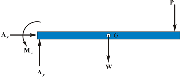
Free Body Diagrams (FBD) will be defined. I've got a representation of that canti, what we call a cantilever beam. So first thing I did was identify the body of interest. Free body diagrams may not seem necessary in the relatively simple current applications, but as problems become more complex, their usefulness The following is the process for determining the reaction at the wall for a cantilever beam. A FBD is first drawn of the beam. Next, cut the beam free...
7 hours ago Cantilever Free Body Diagram Example by SpoonFeedMe. Draw the free body diagram for the cantilevered beam a is the a fixed support the above diagrams which show the complete system of applied and reactive forces acting on a body are called free body diagrams.

Free body diagram of cantilever beam
A free body diagram consists of a diagrammatic representation of a single body or a subsystem of bodies isolated from its surroundings showing all the forces acting on it. In physics and engineering, a free body diagram (force diagram, or FBD)... Free-body diagram of left-hand half of beam: Point E is at the midpoint of the beam. Problem 4.5-22 The cantilever beam shown in the figure supports a concentrated load and a segment of uniform load. Draw the shear-force and bending-moment diagrams for this cantilever beam. Free-body diagram of left-hand half of beam: Point E is at the midpoint of the beam. q A b L/2 RB E V M = 0 (Given). Problem 4.5-4 The cantilever beam AB shown in the figure is subjected to a concentrated load P at the midpoint and a counterclockwise couple of moment M1 PL/4 at the free end.
Free body diagram of cantilever beam. A beam supported by a column and a knee frane hinged cantilever beam with cable support. As with all calculations care must be taken to kee... The free-body-diagram of a typical element of the beam remains the same. as depicted in Fig. Consider the problem of an isotropic cantilever beam of rectangular cross section 2h×b (height 2h and width b), bent by an upward transverse load F0 applied at the free end, as shown in. Free Body Diagram Of A Differential Beam Element. Beam Reactions And Diagrams U2013 Strength Of Materials. 4 Draw The Shear And Moment Diagrams You are simply capable of wire CAT6 cable to RJ-forty five connectors without any challenge. Free Download Cantilever Beam Body Diagram... Cantilever beams and simple beams have two reactions (two forces or one force and a couple) and these reactions can be obtained from a free-body A free body diagram of the portion of the beam between the left end and plane a-a is shown in Fig. 3.3. A study of this section diagram reveals that a...
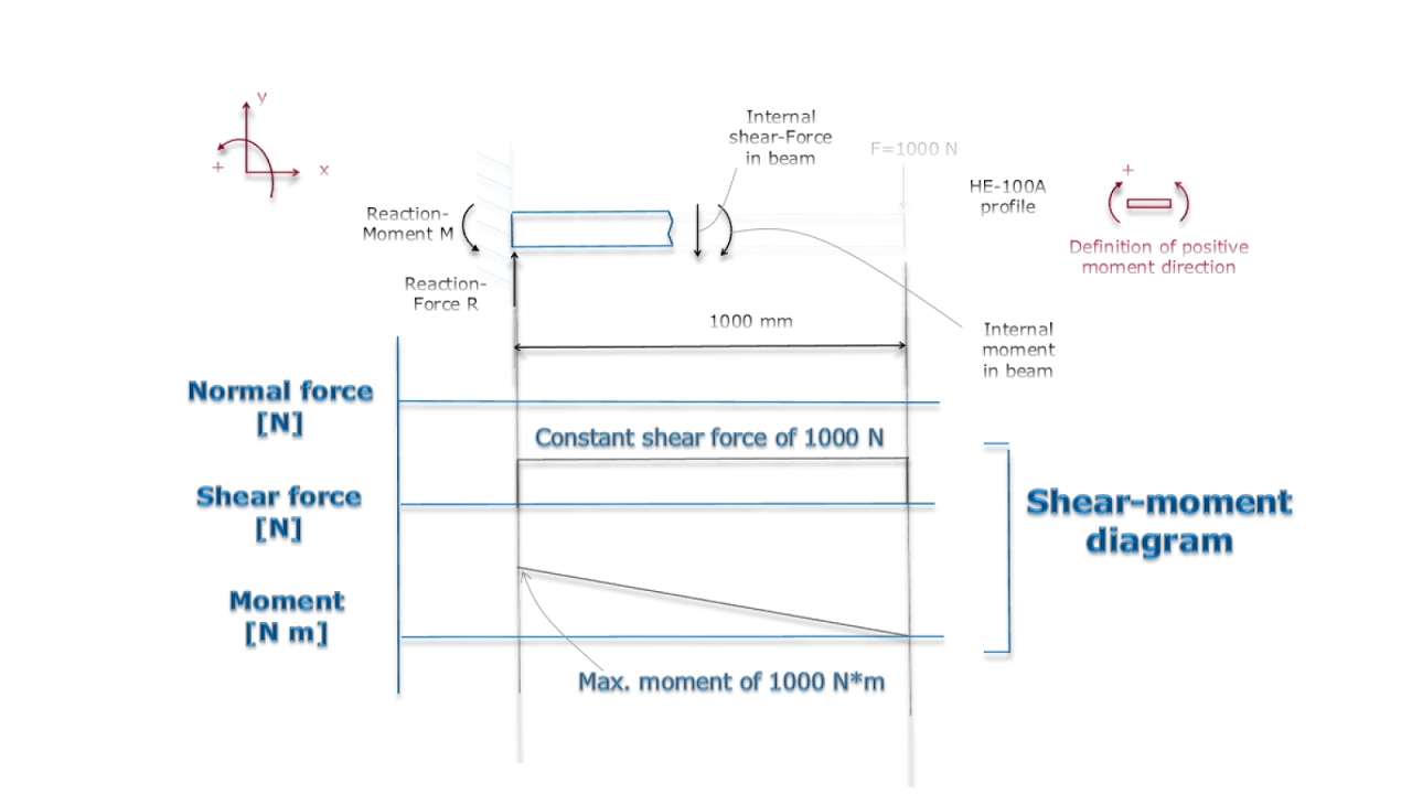
Bending moment diagram and shear force diagram of a cantilever beam having point load at the end,several point load,u.d.l. over whole ,from support to A shear force diagram is the graphical representation of the variation of shear force along the length of the beam and is abbreviated as S.F.D. They can be determined, however, by considering the free-body diagram of each beam separately; six unknowns are involved (including two force components at the hinge), and six equations are available. It was shown in Sec. 4.1 that if we pass a section through a point C of a cantilever beam supporting a... Of a cantilever beam having point load at the endseveral point loadsudl. Online calculator for simply supported and. Figure 6 : Free-Body Diagram of the mass spring system. Free vibration of a cantilever beam experimental acceleration. Figure 11 : Experiment 1 setup with computer experimental acceleration results.
The free-body diagram of the system is. APPENDIX C Cantilever Beam III Consider a cantilever beam where both the beam mass and the end-mass are significant. APPENDIX D. Cantilever Beam IV This is a repeat of part II except that an exact solution is found for the differential equation. For a cantilever beam subjected to free vibration, and the system is considered as continuous system in which the beam mass is 4.1(a) shows of a cantilever beam with rectangular cross section, which can be subjected to bending vibration by giving a small initial displacement at the free end; and Fig. Введите запрос. Войти. Cantilever Free Body Diagram Example | Statics. Смотреть позже. Moving on, the video calculates the moment at cantilever support point developed by the point load subjected to the cantilever beam. The cantilever beam is one of the most simple structures. It features only one support, at one of its ends. Removing the singe support or inserting an internal hinge, would render the cantilever beam into a mechanism: a body the moves without restriction in one or more directions.
Overhead Road Bridge, Newcastle/Gateshead, Tyne & Wear, England.
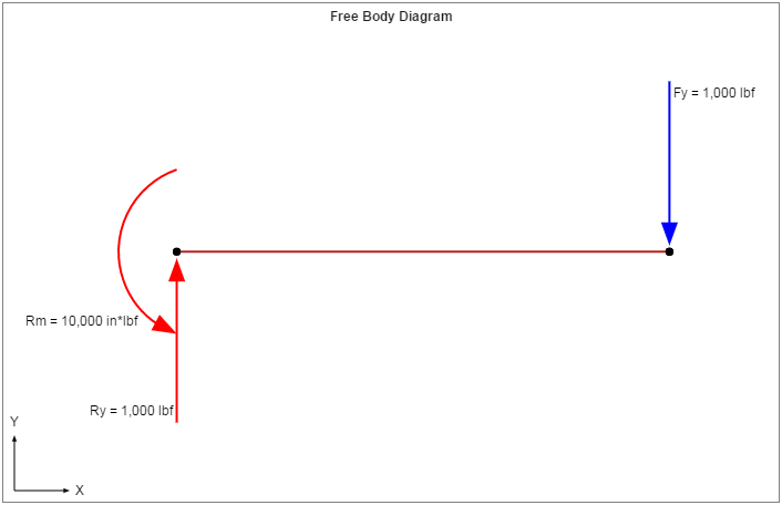
Figure 2: Free Body Diagram of Cantilever Beam with Integrated F. 2. MC Tubes The influence of surface roughness for medium carbon steel at fatigue test on the S-N diagram (Iraq). Three-. dimensional finite element simulation of arc welding process using ANSYS APDL program (Iraq).

Monochrome, Road Network & Scotswood Bridge, Tyne & Wear, England.
2. Cantilever beam subjected to self-balanced moment and end loads. Please cite this article as: A. Banerjee, et al., Large deection of cantilever beams with geometric non-linearity: Analytical and numerical approaches, Int. 3. Free body diagram of the three segments of the cantilever beam.
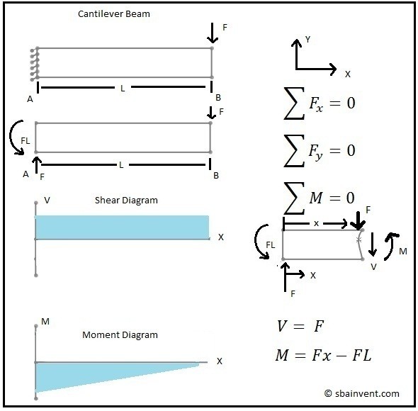
Shear and Moment Diagrams - S.B.A. Invent
Free online beam calculator for cantilever or simply supported beams. However, values of sf and bm can be verified at the support if support reactions are known. Determine (a) the unknown reactions at the wall or fixed support, and (b) draw the free body diagram of the beam, the shear force and the...
Board breaking, part two - All this
‰A cantilever beam is built into a rigid support at one end, with the other end being free, as shown in Fig.4.1(b). The built-in support prevents ‰ The determination of the internal force system acting at a given section of a beam : draw a free-body diagram that expose these forces and then compute the...
Solved: Draw A Free Body Diagram Of The Cantilevered Beam ...
Cantilever Beam Shear And Moment Diagram Youtube. Moment Diagram Cantilever Beam Civil Engineering Archive November. Free Body Diagram On Incline.
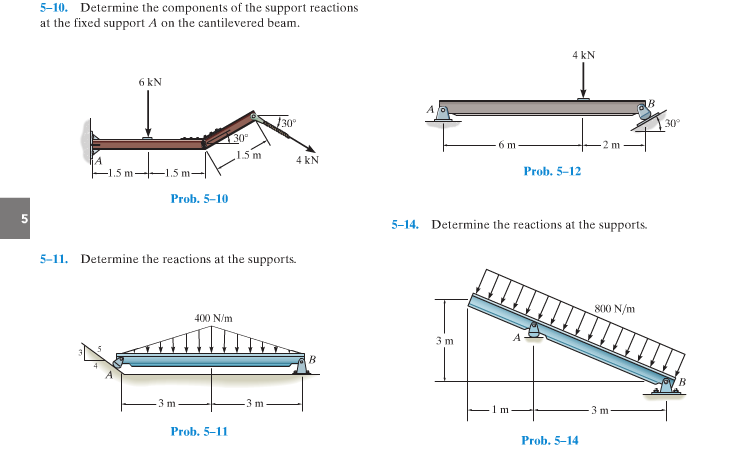
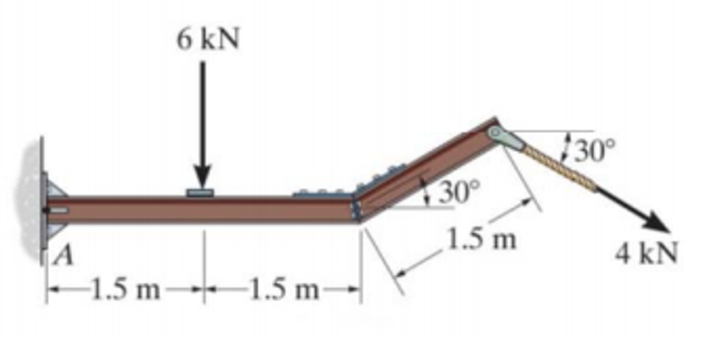
Solved: Determine The Components Of The Support Reactions ...
This beam calculator is designed to help you calculate and plot the Bending Moment Diagram The tool is fully functional, so visit our Beam Calculator and Frame and Truss Calculator to get started! Thank you for free beam calculator. Its really helping. You're rock guys. Maybe it would be much...

Blaydon Railway Bridge, Newcastle/Gateshead, Tyne & Wear, England.
Include all relevant geometry with consistent notation. The tare value is 0.140 V and Vs is 4.900 volts and the Amplification factor is 500 and the gage factor is 2.1. Calculate and report the strain at the strain gage. 2. The material of the beam is 6061 T6 Aluminum, with a yield point.

Monochrome, Scotswood Bridge & Blaydon Railway Bridge, Tyne & Wear, England.
Characterising Modal Behaviour of a Cantilever Beam at Different Heating Rates for Isothermal Conditions. The inertia force in the beam element can be expressed using the free-body diagram as
Shear Force and Bending Moment Diagrams for an INTERESTING ...
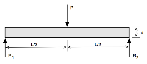
Cantilever Beam - Single Load Calculator. Add standard and customized parametric components - like flange beams, lumbers, piping, stairs and more - to your Sketchup model with the Engineering ToolBox - SketchUp Extension - enabled for use with the amazing, fun and free SketchUp Make and...
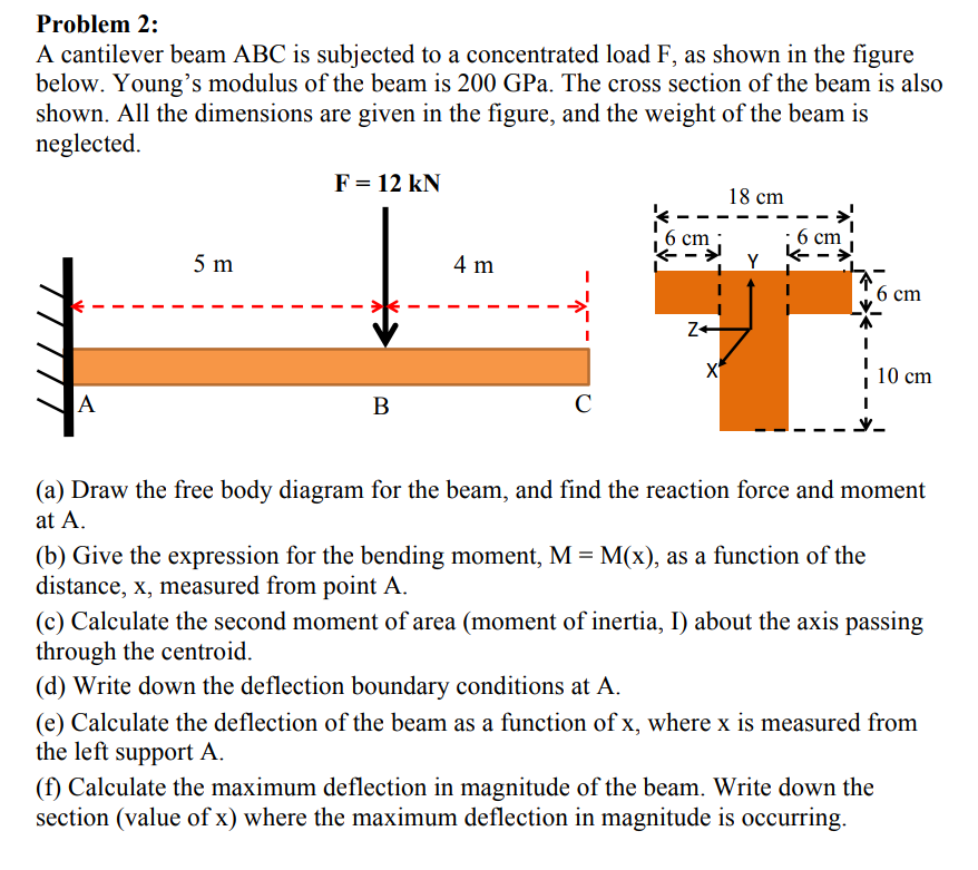
Solved: Problem 2: A Cantilever Beam ABC Is Subjected To A ...
Welcome to our free online bending moment and shear force diagram calculator which can generate the Reactions, Shear Force Diagrams (SFD) and Bending Moment Diagrams (BMD) of Any changes made will automatically re-draw the free body diagram any simply supported or cantilever beam.
Determining the Shear Force and Bending Moment Equations ...
The cantilever is a beam which has one end free and the other is fixed. In the case of cantilever shown in figure 5-1(a), there is no horizontal force and hence the fixed support will have only two reaction components (one vertical Dy and the other moment MD) as shown in the free body diagram...
35 Cantilever Beam Free Body Diagram - Wiring Diagram Database
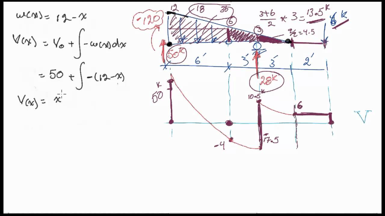
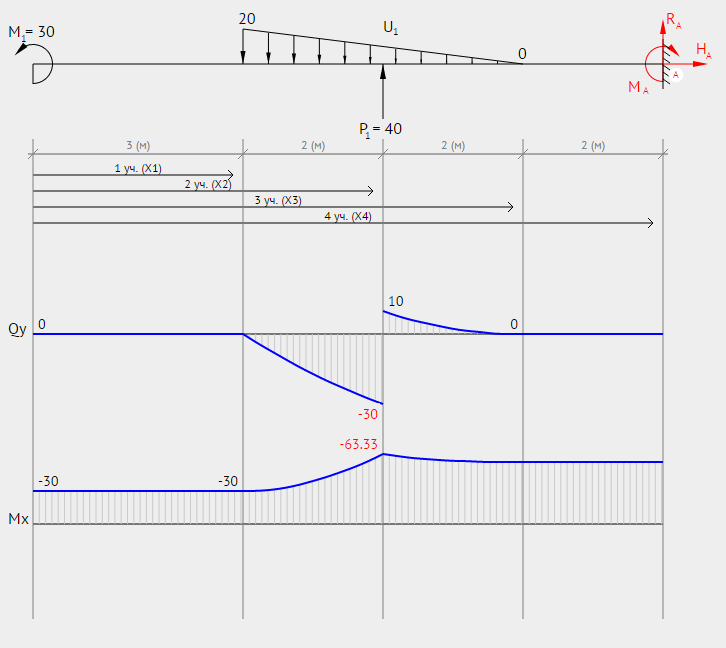
Fbd = free body diagram. A case of cantilever beam with u.v.l. 63 sfd bmd 30kn 10kn 50kn parabola x = 1.5 m parabola 20knm 10knm point of contra Free online beam calculator for cantilever or simply supported beams. 5 most imp points to keep in mind for shear force and bending moment diagrams.

Reactive moments in a cantilever beam modeled with 3-D ...
Free-body diagram of left-hand half of beam: Point E is at the midpoint of the beam. q A b L/2 RB E V M = 0 (Given). Problem 4.5-4 The cantilever beam AB shown in the figure is subjected to a concentrated load P at the midpoint and a counterclockwise couple of moment M1 PL/4 at the free end.
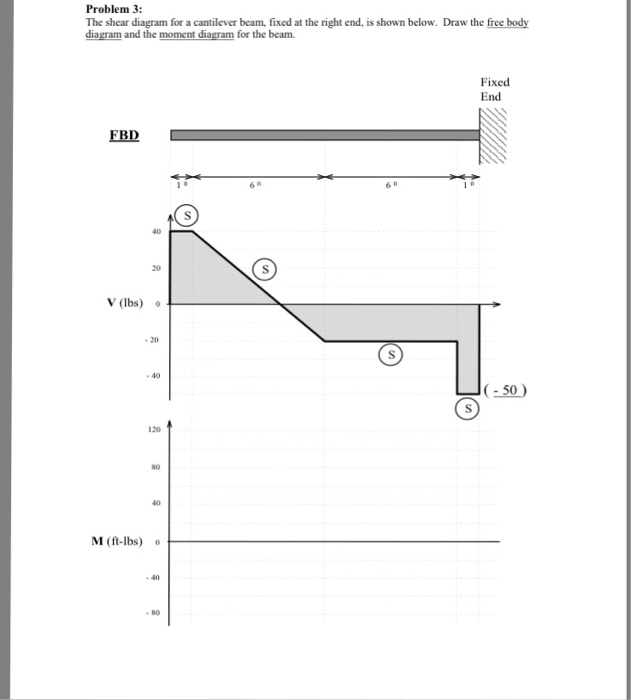
Solved: Problem 3 The Shear Diagram For A Cantilever Beam ...
Free-body diagram of left-hand half of beam: Point E is at the midpoint of the beam. Problem 4.5-22 The cantilever beam shown in the figure supports a concentrated load and a segment of uniform load. Draw the shear-force and bending-moment diagrams for this cantilever beam.

(a) Cantilever beam model; (b) free-body diagram; (c) a ...
A free body diagram consists of a diagrammatic representation of a single body or a subsystem of bodies isolated from its surroundings showing all the forces acting on it. In physics and engineering, a free body diagram (force diagram, or FBD)...

Cantilever Beam Free Body Diagram - Hanenhuusholli

Monochrome, Scotswood Bridge, Tyne & Wear, England.

Solved: As Shown, A Solid Beam Is Supported By A Roller At ...
Chapter 6 Solutions | Engineering Mechanics, Statics 2nd ...
29 Cantilever Beam Free Body Diagram - Wire Diagram Source ...

Shear Force and Bending Moment Diagram for Cantilever Beam ...
Why do we provide stirrup or web reinforcement closely at ...

Blaydon Railway Bridge & Scotswood Bridge, Newcastle/Gateshead, Tyne & Wear, England.
Definition Of A Cantilever - Tile Design Ideas

Eiffel Tower...Tightrope walking

Statics eBook: Indeterminate Objects

Cantilever beam discretized by a finite difference ...
Solved: Part A - Reactions At Support C Draw A Free-body D ...
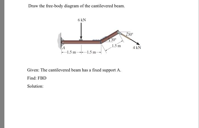
Solved: Draw The Free-body Diagram Of The Cantilevered Bea ...
29 Cantilever Beam Free Body Diagram - Wire Diagram Source ...
Solved: Draw The Free-body Diagram For The Cantilevered Be ...
ANALISA STRUKTUR 4: Apa yang dimaksud Free Body Diagrams?

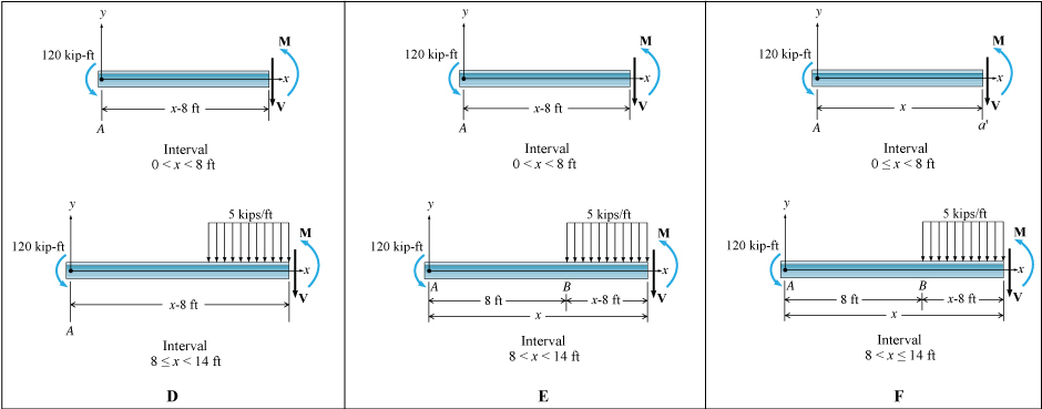
Example 6 For the cantilever beam loaded as shown, a ...
Beam Analysis - Validation | MechaniCalc

Monochrome, Blaydon Railway Bridge, Tyne & Wear, England.
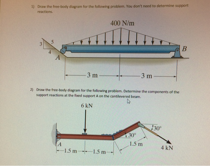
Solved: Draw The Free-body Diagram For The Following Probl ...

35 Cantilever Beam Free Body Diagram - Wiring Diagram Database
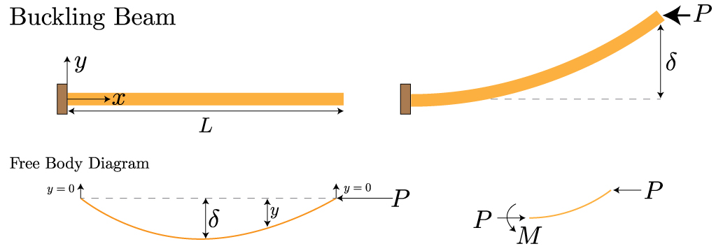
Mechanics of Materials: Beam Buckling » Mechanics of ...
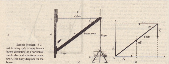
Sample Problem Physics Homework Help, Physics Assignments ...

Double Cantilever Beam Moment Equation - Tessshebaylo


Comments
Post a Comment